

Reviving the Smart ATX
Reviving a 3D-printed LED arch lamp: powering it from an ATX supply via an ESP32, and replacing the dead FauxmoESP/Alexa control with ESPHome + Home Assistant.

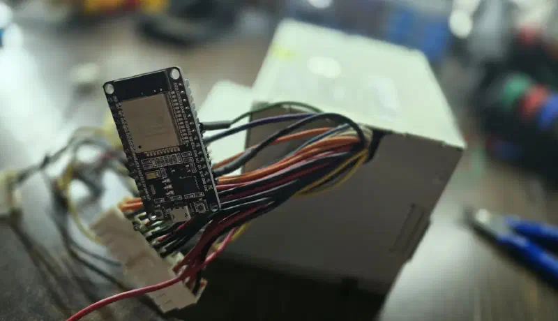
Back in early 2020, Alexa and Google Home were the hot thing. I spent far too many hours setting up my smart-home gear. This was before I lost faith that these companies could/would keep my data private and secure. I later switched to hosting everything locally and using Home Assistant.
But during that time I had 3D printed a custom LED arch lamp. And I had a bunch of old ATX computer power supplies. These are perfect for clean power, low voltage, and high current. They also have clean on/off switching and overcurrent protection. So naturally I grabbed one and set it up to power this light. The only problem is I wanted to control it with my other smart devices.
Now you might be tempted to throw a smart plug on it and call it a day. But ATX power supplies don’t like to be power cycled like that. Instead, there is a control line that when tied to ground enables the outputs. There also happens to be a standby, always-on line. It’s just begging to be controlled by a microcontroller.
So that’s what I did. I grabbed a random ESP32 lying on my bench and started figuring out how I was going to link it to my Alexa. As it turned out, someone already thought of this and made the FauxmoESP project. It tricked Alexa into thinking it was a Philips Hue bulb. Why a Hue bulb? It was one of the few that Alexa could control locally without having to go through an online server. And it worked really well for several years until one day it didn’t. Alexa started changing how it did device discovery and broke the old protocol. Trying to chase the protocol updates was annoying and eventually it wound up on the shelf. (If you are curious what that old firmware looked like, you can still find it in the git history.)
Running Home Assistant gives me way more integration options, lets me keep my control and data local, and does so much more than my old setup ever did.

So why not update this old thing with ESPHome and bring it to life again? ESPHome is a configurable firmware for the ESP32 to be a controller for all sorts of devices. You configure it by uploading a YAML file that defines the pins and functionality.

Home Assistant and other ecosystems auto-discover its capabilities, and you are off and running.
I figured I would do a writeup for those interested in setting up something similar.
The wiring
First, let’s figure out the wiring.
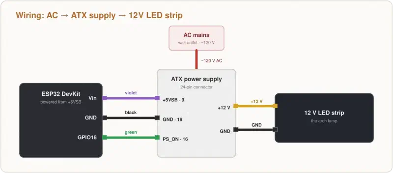
| ESP32 pin | ATX wire | Details |
|---|---|---|
| Vin | +5VSB (Violet) | The +5VSB line from the power supply is an always-on, low-current 5V line. We connect it to the Vin pin on this board, which powers the on-board regulator and provides 3.3V to the ESP32. |
| GND | GND (Black) | All grounds need to be connected to have a return path for current and have a common potential to work from. |
| GPIO18 | PS_ON (Green) | When the enable line is pulled down to GND, the power supply powers up. It’s our control line. Otherwise we release the line and let it float (around 3.8V on this PSU). |
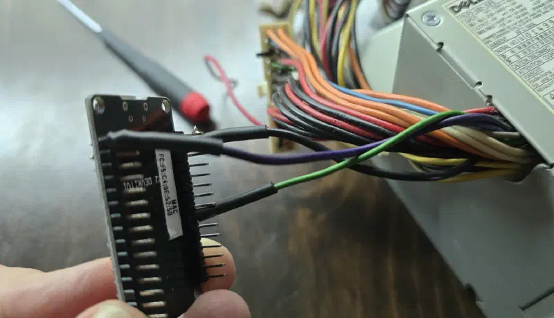
As you can see, I didn’t bother to make a case for the ESP32 for this quick hack. I just soldered the wires directly onto the header pins and shrink-tubed the wires. All these wires are low voltage and have short protection; there’s little risk to people here. Still, wires could get hot if shorted through a high-resistance joint, so be mindful. But generally the worst that happens is something on the board gets shorted and the board dies. It’s sitting on a soldering bench, so it fits right at home. Now inside the power supply is another matter. Don’t open that up unless you know how to work with high voltage.
One last electrical note. With the ESP32’s pin floating, PS_ON sits at about 3.8V and draws next to nothing — under 1mA, basically 0mA on my meter. Pulling it to ground to turn the supply on draws about 1mA. That 3.8V is a touch above the ESP32’s input rating, but at that tiny current it’s been perfectly happy — this setup has run for years without issue. If you want to do it properly, you could add a small N-channel MOSFET on the line as a buffer, so the ESP32 never sees the supply’s voltage directly.
The ESPHome config
Instead of writing the firmware directly, ESPHome manages its configurations with a YAML config file. Below you will find the config I had Claude Code research and generate for me based on the review of my old code. This made it super fast and easy to convert.
# =============================================================================
# Smart ATX Bench Supply — ESPHome configuration
#
# An ESP32 turns a scrap PC (ATX) power supply into a bench supply switchable
# from Home Assistant. It works because of one trick:
#
#   An ATX supply's main rails stay off until PS_ON (pin 16, green) is pulled
#   to ground — but a controller can't ground it without power. The +5VSB rail
#   (pin 9, violet) is always live, even with the supply "off", so it powers
#   the ESP32, which then grounds PS_ON on command.
#
# Wiring (unchanged from the 2020 build):
#
#   ESP32 pin  | ATX 24-pin  | Wire   | Purpose
#   -----------|-------------|--------|-----------------------------------------
#   Vin        | pin 9       | violet | +5VSB, always-on standby rail
#   GND        | pin 19      | black  | ground
#   GPIO18     | pin 16      | green  | PS_ON — ground it to start the supply
#
# Replaces the original FauxmoESP firmware, which emulated a Philips Hue bulb
# so Alexa could discover it over SSDP. Newer Echo devices stopped finding it.
# Voice control now rides Home Assistant instead of any on-device emulation.
#
# The build write-up, including how the board was identified and the PS_ON
# voltage caveat, is on the project website. See the README.
# =============================================================================

substitutions:
  device_name: smart-atx
  friendly_name: "Smart ATX Bench Supply"

  # --- Hardware-specific values ---------------------------------------------
  # These two are the only board-dependent settings in this file. If you are
  # adapting this to a different ESP32 board, these plus `board:` below are all
  # you need to change.

  # Drives PS_ON. Must be a pin that boots high-impedance — GPIO18 is not a
  # strapping pin, so it floats during the boot window before ESPHome takes
  # over, which keeps the supply off. Do not move this to GPIO0, 2, 5, 12 or 15
  # without checking the ESP32 strapping-pin table first.
  ps_on_pin: GPIO18

  # Onboard blue LED on the DevKit V1. GPIO2 is a strapping pin, but it only
  # matters at boot, and this board's LED sits between the pin and ground so it
  # can't hold the pin high while the ESP32 samples it. Driving it as an output
  # afterwards is fine.
  #
  # ESPHome prints "GPIO2 is a strapping PIN" on every build because of this.
  # The warning is expected and is left visible on purpose rather than silenced
  # with `ignore_strapping_warning: true` -- if you adapt this to a board whose
  # LED is wired to 3.3 V instead of ground, that warning is one you want to
  # see.
  status_led_pin: GPIO2

esphome:
  name: ${device_name}
  friendly_name: ${friendly_name}
  comment: "ATX bench supply — ESP32 on +5VSB grounds PS_ON"

esp32:
  # PlatformIO board ID for the ESP32 DEVKIT V1, confirmed against the
  # physical board on 2026-09-14. The 2020 build never recorded which board it
  # used; the write-up covers how it was identified.
  # Adapting to a different board: change this line and status_led_pin above.
  # Nothing else depends on it.
  board: esp32doit-devkit-v1
  framework:
    type: esp-idf

logger:
  level: INFO

# Native API — this is how Home Assistant talks to the device. No cloud, no
# Hue emulation, no SSDP. The encryption key lives in secrets.yaml.
api:
  encryption:
    key: !secret api_encryption_key

# Over-the-air updates, so the ESP32 can be reflashed while wired into the
# supply. The first flash must still be over USB.
ota:
  - platform: esphome
    password: !secret ota_password

wifi:
  ssid: !secret wifi_ssid
  password: !secret wifi_password

  # If the network is unreachable, raise an AP so the device can be recovered
  # without unwiring it. The supply stays OFF the whole time — see the switch
  # definition below.
  ap:
    ssid: "${friendly_name} Fallback"
    password: !secret ap_password

captive_portal:

# Backs the free-heap and reset-reason diagnostics further down.
debug:
  update_interval: 60s

# -----------------------------------------------------------------------------
# Outputs
# -----------------------------------------------------------------------------
output:
  # Onboard LED, driven from the switch's automations so it mirrors the supply.
  # Gives an at-a-glance state at the bench without opening Home Assistant.
  - platform: gpio
    id: status_led_output
    pin: ${status_led_pin}

# -----------------------------------------------------------------------------
# The supply itself
# -----------------------------------------------------------------------------
switch:
  - platform: gpio
    id: atx_psu
    name: "Power"
    icon: "mdi:power-plug"

    pin:
      number: ${ps_on_pin}

      # OPEN DRAIN — this is the safety-critical part of the whole config.
      #
      # The pin can only pull PS_ON low or let go of it entirely; it can never
      # drive PS_ON high. The supply's own internal pull-up (~3.8 V, measured)
      # defines the "off" state. This mirrors what the 2020 sketch did by
      # toggling pinMode() between INPUT (float = off) and OUTPUT+LOW (on).
      #
      # A plain push-pull output would be wrong: it would actively drive PS_ON
      # to 3.3 V against the supply's 3.8 V pull-up, fighting it and sourcing
      # current into the PSU's control input.
      #
      # 3.8 V is above the ESP32's absolute-maximum input (VDD + 0.3 V = 3.6 V),
      # though only slightly, and the measured current is under 1 mA. Other
      # supplies differ -- the ATX specification pulls PS_ON up to +5VSB, so
      # measure your own before assuming it is this gentle.
      mode:
        output: true
        open_drain: true

      # Open drain writes LOW to pull down and HIGH to release. Switch "on"
      # must pull PS_ON down, so the logic is inverted.
      #
      # Net effect, which is what matters here:
      #   OFF -> gpio_set_level(18, 1) -> pull-down FET off -> pin floats
      #   ON  -> gpio_set_level(18, 0) -> pull-down FET on   -> pin at GND
      #
      # This is one static pin mode (GPIO_MODE_OUTPUT_OD), not a mode toggle.
      # The 2020 sketch got the same two states by switching pinMode() between
      # INPUT and OUTPUT; open drain reaches them without ever reconfiguring
      # the pin, and leaves the input buffer disabled so ESP32 lets the power
      # supply pull the line up and the ESP32's pin is just floating.
      #
      # Boot-order note: the ESP32's GPIO_OUT register resets to 0, so enabling
      # an open-drain output before writing a level would momentarily pull
      # PS_ON low and kick the supply on. ESPHome avoids this — GPIOSwitch
      # setup() writes the off state *before* it configures the pin, then
      # writes it again after. Before ESPHome runs at all, GPIO18's reset
      # default is high-impedance input with pulls disabled, so the supply
      # stays off through the whole boot window.
      inverted: true

    # ALWAYS_OFF, not RESTORE_DEFAULT_OFF. After a power blip, crash, or
    # reflash, the supply must come back OFF — never resume on its own into a
    # load nobody is standing next to.
    restore_mode: ALWAYS_OFF

    on_turn_on:
      - output.turn_on: status_led_output
    on_turn_off:
      - output.turn_off: status_led_output

# -----------------------------------------------------------------------------
# Diagnostics — none of these can affect the supply's state
# -----------------------------------------------------------------------------
sensor:
  - platform: uptime
    type: seconds
    name: "Uptime"
    entity_category: diagnostic

  - platform: wifi_signal
    name: "WiFi Signal"
    update_interval: 60s
    entity_category: diagnostic

  - platform: debug
    free:
      name: "Heap Free"
      entity_category: diagnostic

text_sensor:
  - platform: debug
    reset_reason:
      name: "Reset Reason"
      entity_category: diagnostic

button:
  - platform: restart
    name: "Restart"
    entity_category: diagnostic
It’s important here that the pin controlling the power supply enable line (green wire) is configured as an open drain. This means that the pin will actively pull down to ground with a 0 or let the line float and not pull it any way with a 1. The power supply has its own internal pullup and we don’t want to try driving this line. We only want to pull it down to ground to enable the power supply. This is called an open drain configuration.
The 2020 version of this achieved this by setting the pin as an output and low when turning the power supply on. To turn the power supply off, it would change the pin mode to input which lets the pin float.
Flashing ESPHome
There are several ways to flash the ESPHome firmware onto the ESP32. Home Assistant has a plugin you can install for ESPHome Builder. You can use online flashers like web.esphome.io. Or you can set up a local instance of ESPHome builder which is the route I will be showing.
In order to make the builder recognize your configuration and project, you must put two files in your project folder. smart-atx.yaml, and a secrets.yaml. You can find these files (a template for secrets.yaml) in this project repo. The secrets.yaml file holds your private values. The smart-atx.yaml file references each one with !secret, so those values stay out of the shared file:
# secrets.yaml
wifi_ssid: "your-network-name"        # the Wi-Fi network the ESP32 joins
wifi_password: "your-wifi-password"   # that network's password
api_encryption_key: "..."             # 32-byte base64 key Home Assistant uses to talk to the device
ota_password: "..."                   # password for over-the-air reflashes (after the first USB flash)
ap_password: "..."                    # password for the fallback hotspot raised if Wi-Fi is unreachable
The api_encryption_key is just a random 32-byte value in base64, you can generate one many ways. Below are some examples:
macOS / Linux:
openssl rand -base64 32Windows (PowerShell):
$bytes = New-Object byte[] 32; [System.Security.Cryptography.RandomNumberGenerator]::Create().GetBytes($bytes); [Convert]::ToBase64String($bytes)Any OS with Python:
python3 -c "import secrets, base64; print(base64.b64encode(secrets.token_bytes(32)).decode())"Each prints a 44-character key ending in =. Paste it into secrets.yaml as your api_encryption_key. You will use the same key later to add the device to Home Assistant.
Now to install ESPHome’s web dashboard. You can install it without the dashboard and do everything on the command line, but I find it easier to use a GUI months later than trying to remember the syntax of a command you might run every few months.
uv tool install --python 3.14 'esphome-device-builder[esphome]'
uv tool install --python 3.14 esphome  # the CLI, so `esphome run` works later
In this example I pinned Python 3.14 with --python 3.14 because in my environment it defaulted to an older version of ESPHome builder. This will certainly be out of date in the future so you might want to omit it or update it to the latest version for your setup.
From your project folder with your files in it run the following. For example, I will be using a folder called esp-light in my home directory. Make sure to use your own folder location.
cd ~/esp-light
esphome-device-builder --host 127.0.0.1 .
Now open the web interface from the same computer: http://localhost:6052
The trailing . matters — without it the Device Builder looks in ./configs, finds nothing, and shows an empty first-run screen. --host 127.0.0.1 keeps it local, binding to loopback and preventing people external to your computer from opening it remotely; by default it binds every interface with no authentication.
Before anything is flashed, the device shows Offline and is normal. Nothing is programmed or online and communicating yet.
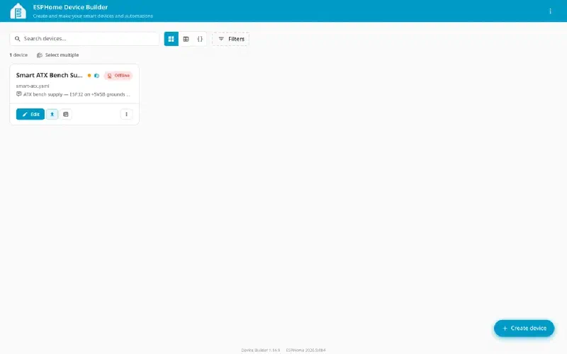
Click Install. The first flash has to be over USB; later updates can go over the network:
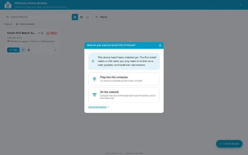
Unplug the ATX supply from mains before you connect USB. On most ESP32 devkits VIN and USB’s 5 V are directly connected with no isolation. This allows the two supplies to fight each other and will likely end with your laptop USB ports shutting down or possibly becoming damaged.
Under Advanced options you can also target a specific IP, or just download the compiled .bin to flash elsewhere, like with a web-based flasher:
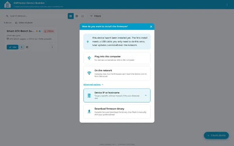
Pick Plug into this computer, choose the serial port, and let it run. (Web Serial needs Chrome or Edge. As of this writing it doesn’t work in Firefox or Safari.)
If you’d rather skip the browser, you can also run the following from your terminal:
esphome run smart-atx.yamlUse
esphome run, notesphome upload—uploadflashes the last binary it built without recompiling, so it will happily write a stale image after you’ve changed your Wi-Fi credentials. Ask me how I know.
Reset the board and it should join your Wi-Fi. If you need to debug the board, you can open a serial terminal like PuTTY and look at its boot messages:
[I][app:151]: ESPHome version 2026.8.2 compiled on 2026-09-14 ...
[I][wifi:1609]: Connected
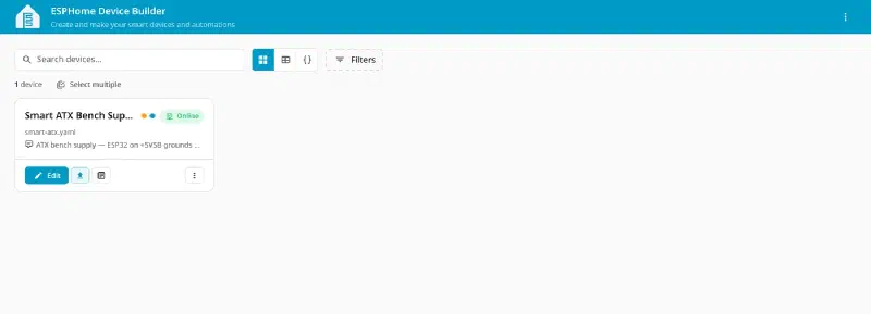
Once the Device Builder can reach it over the API, the badge flips to Online.
Now is a good time to switch off of USB power and back to the power supply. Disconnect the ESP32 from the USB cable and plug in the power supply. You should see the ESP32 boot back up and it should come back online again in the ESPHome Device Builder.
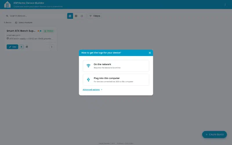
Open Logs. “On the network” streams over the ESPHome API, so it works in any browser:
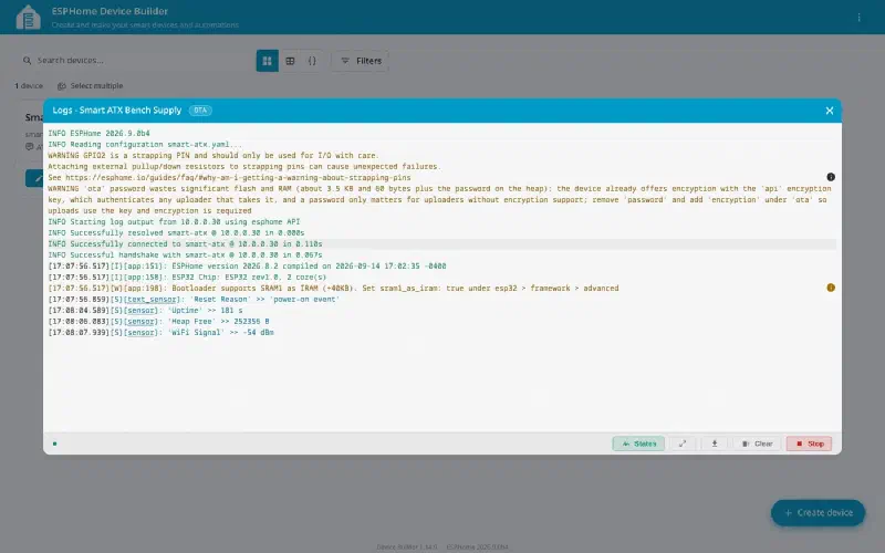
All four diagnostics report, and Reset Reason confirms a clean power-on:
[S][text_sensor]: 'Reset Reason' >> 'power-on event'
[S][sensor]: 'Uptime' >> 181 s
[S][sensor]: 'Heap Free' >> 252356 B
[S][sensor]: 'WiFi Signal' >> -54 dBm
Congratulations! You now have an ESPHome device working and you can now control it from many different ecosystems. ESPHome has its own. Below I will detail connecting it to Home Assistant because that’s what I prefer.
Setting it up in Home Assistant
This article is already long enough, setting up the Home Assistant server and the rest of your smart-home is beyond the scope here. There are many ways to do it. Self hosted (what I am doing), web hosted, you can buy a preconfigured appliance, you can set it up on your own computer, you can run it in a virtual machine, there are a ton of options. See the main page for more detail: https://www.home-assistant.io/
Head to Settings → Devices & services.
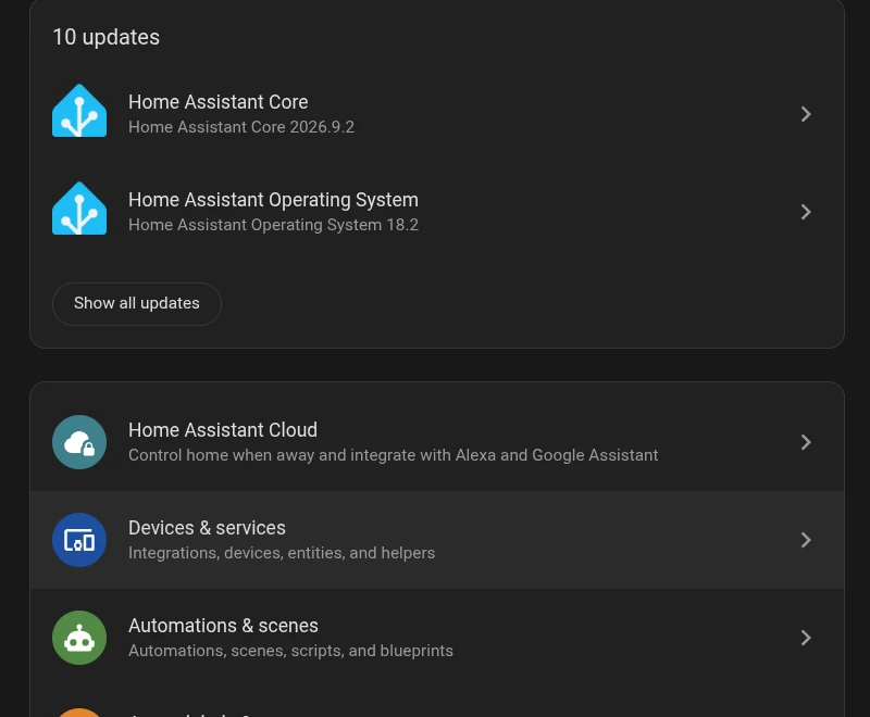
I know, I know, I should really do my updates! 😅
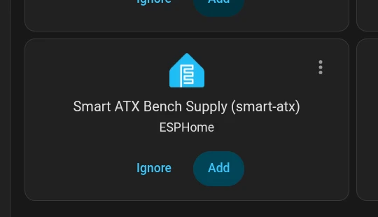
The Smart ATX shows up on its own under Discovered. Click Add.
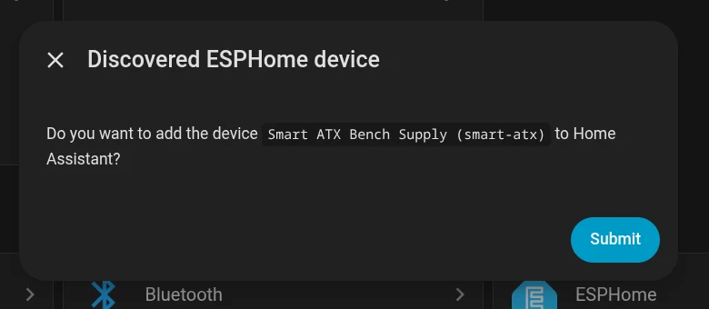
Confirm you want to add it.
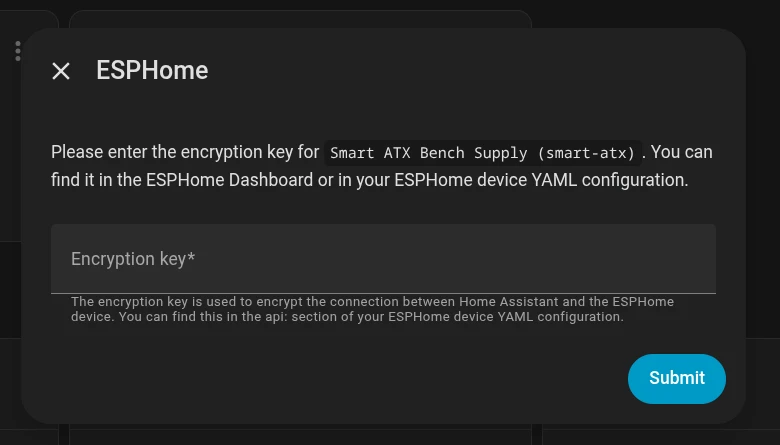
Then paste the encryption key — the same api_encryption_key you generated into secrets.yaml earlier.
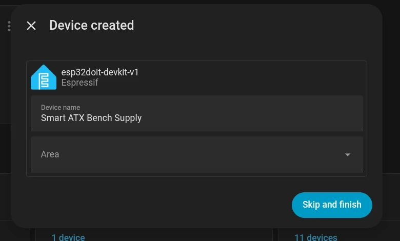
Give it a name, drop it in an area if you like, and finish.
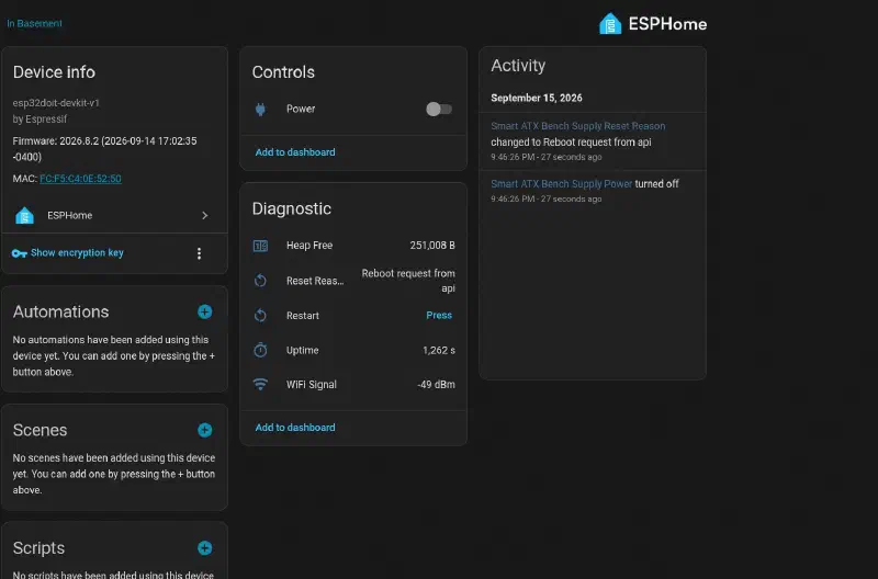
That’s it! It’s now ready to be used in your Home Assistant! No more Alexa in the setup, we own our control and data now.
Here you see the device page with diagnostics like uptime, free heap, Wi-Fi signal, and last reset. You can also control it from here by flipping that switch! But normally you add it to a Home Assistant dashboard instead of coming here. And there you have it, a revived smart ATX power supply!
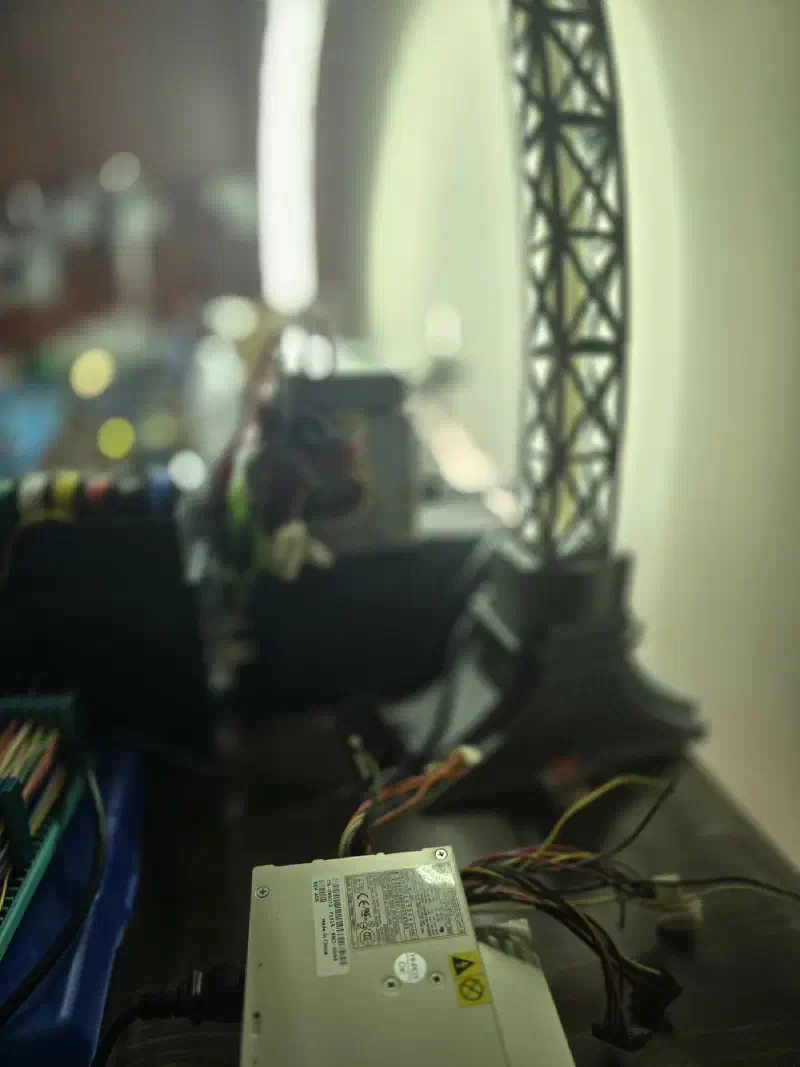
And here it is, switched from the phone:
To think when I started this, I thought this would be a quick small writeup. I’m just flashing ESPHome to an old ESP32 power supply, how much content could there really be? lol Thanks for reading!
Interested in hiring someone to do this for you? → See what I offer